Threat Rules
Threat rules are used multiple times in different sections of the configuration. There are rules for stencils, components, and data flows. Rules for stencils and components can be configured directly in the respective sections. Data flow rules are configured in CPDFD Rules.
General configuration
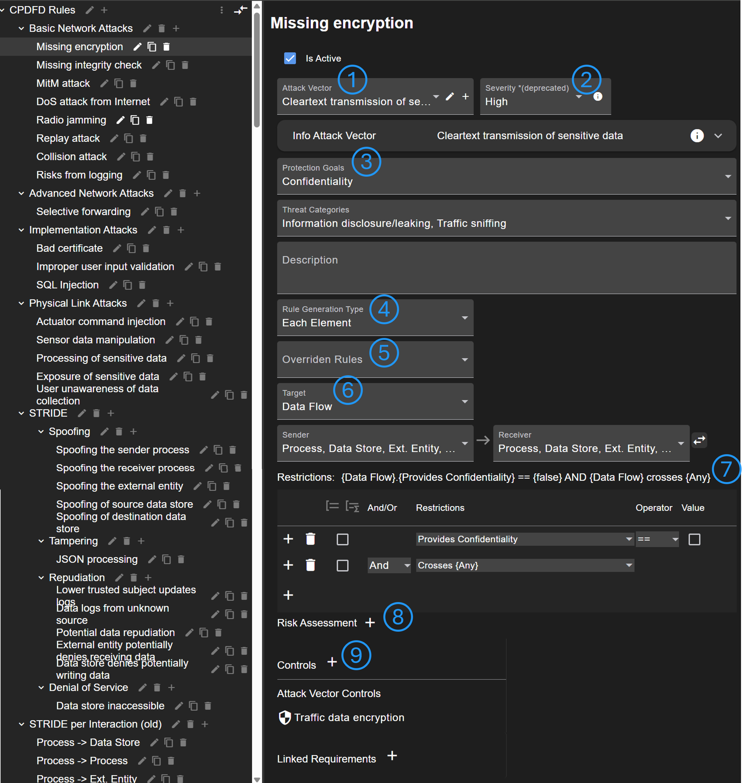
A threat rule can reference to an attack vector that provides further information (No. 1). The severity of the rule can be rated (No. 2), however, this approach is deprecated. Instead, the risk assessment field (No. 8) should be used. More details to the rule can be added (No. 3), e.g. affected protection goal, associated threat categories, and a customizable description.
There are different rule generation types (No. 4). If 'Each Element' is selected, an attack scenario will be created for each element that matches to the rule. 'Once for all elements' can be used if only one attack scenario should be generated that summaries all affected elements. The type 'Once for each pair' generates scenarios in data flow diagrams only once for each pair of sender and receiver.
There is an option to override other rules (No. 5). If a rule applies and an override rule too, the override rule is not generated.
The target of the rule (see No. 6) is shown or configured in case of data flow rules.
It is possible to define a list of restrictions when the rule is generated (see Defining restrictions) (No. 7).
The rating of the risk assessment can be predefined (No. 8). This is useful to automate the risk assessment.
A list of controls can be defined (No. 9). Based on these controls, countermeasures will be generated or referenced. Note that rules inherent controls from attack vectors.
Last, it is possible to link requirements from checklists.
Data flow rules (CPDFD)
As mentioned before, for data flow rules the target can be explicitly defined. The reason is that an attack on data flows always target a group of elements (sender, data flow, receiver, and optionally nodes). The configured target will be shown as affected element in the risk tables.
Furthermore, there are a few more fields for data flow rules.
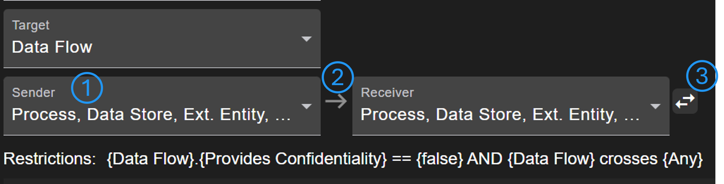
It can be defined which element type the sender, receiver or other nodes must be (No. 1). Using the arrow (No. 2), additional nodes can be inserted in order to define more complex rules with multiple nodes in a communication. With the arrow button (No. 3) it is defined whether data must flow in a specific direction. If apply reverse is active, the rule will be checked in both directions.
Defining restrictions
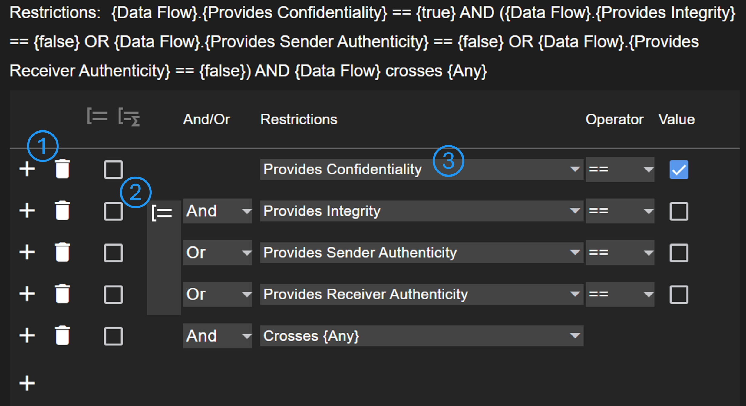
Restrictions are used to check if a rule applies to a certain element. With the add button (No. 1) new restrictions can be added above. Using the checkboxes (No. 2), the selected restrictions can be grouped. A group will be evaluated first, before the result will be evaluated with the higher level. The select in No. 3 is used to configure the condition to be evaluated.
Mostly, the condition is a property of the respective element. For data flows, it can be differentiated between the targets. Furthermore, it can be defined whether a data flow must cross a (specific) trust area.
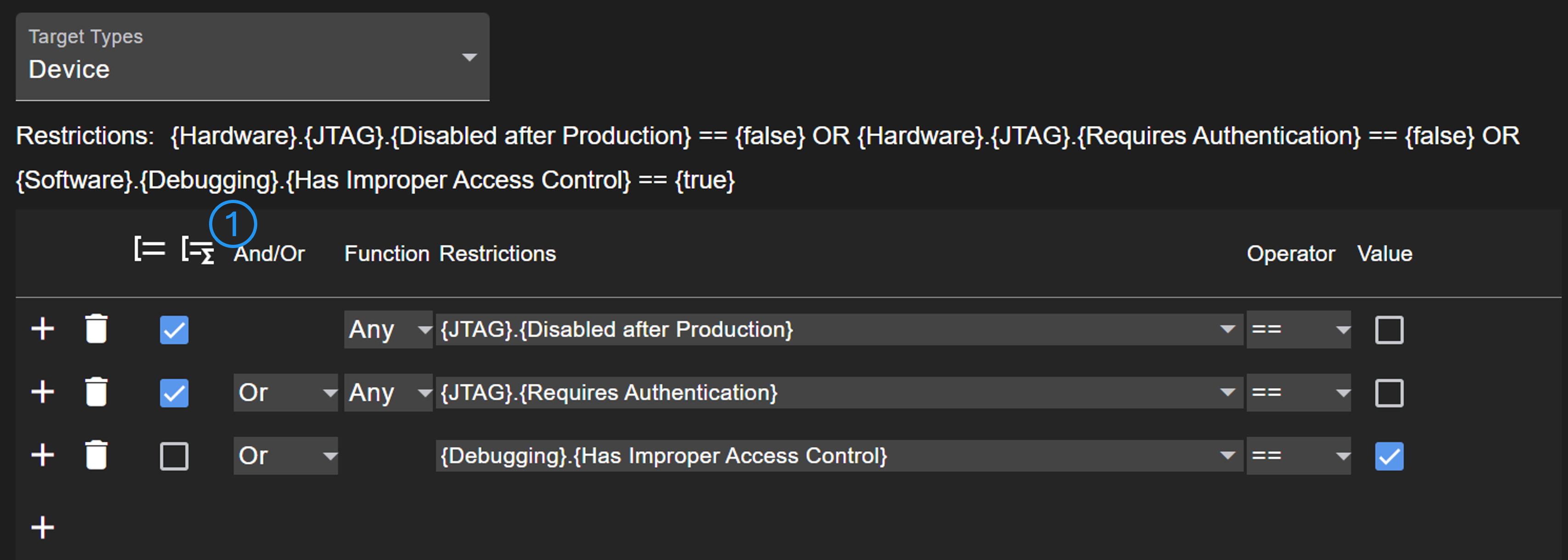
In case of checklists, more complex rules can be defined referencing different models. In hardware diagrams, there could be multiple elements of a type such as JTAG. Therefore, a function (any or all) is applied on matching elements. As there can be a difference if several conditions must be met, it is important when a function is executed. Using the group function button (No. 1), a function can be 'moved' to a higher level.